Introduction
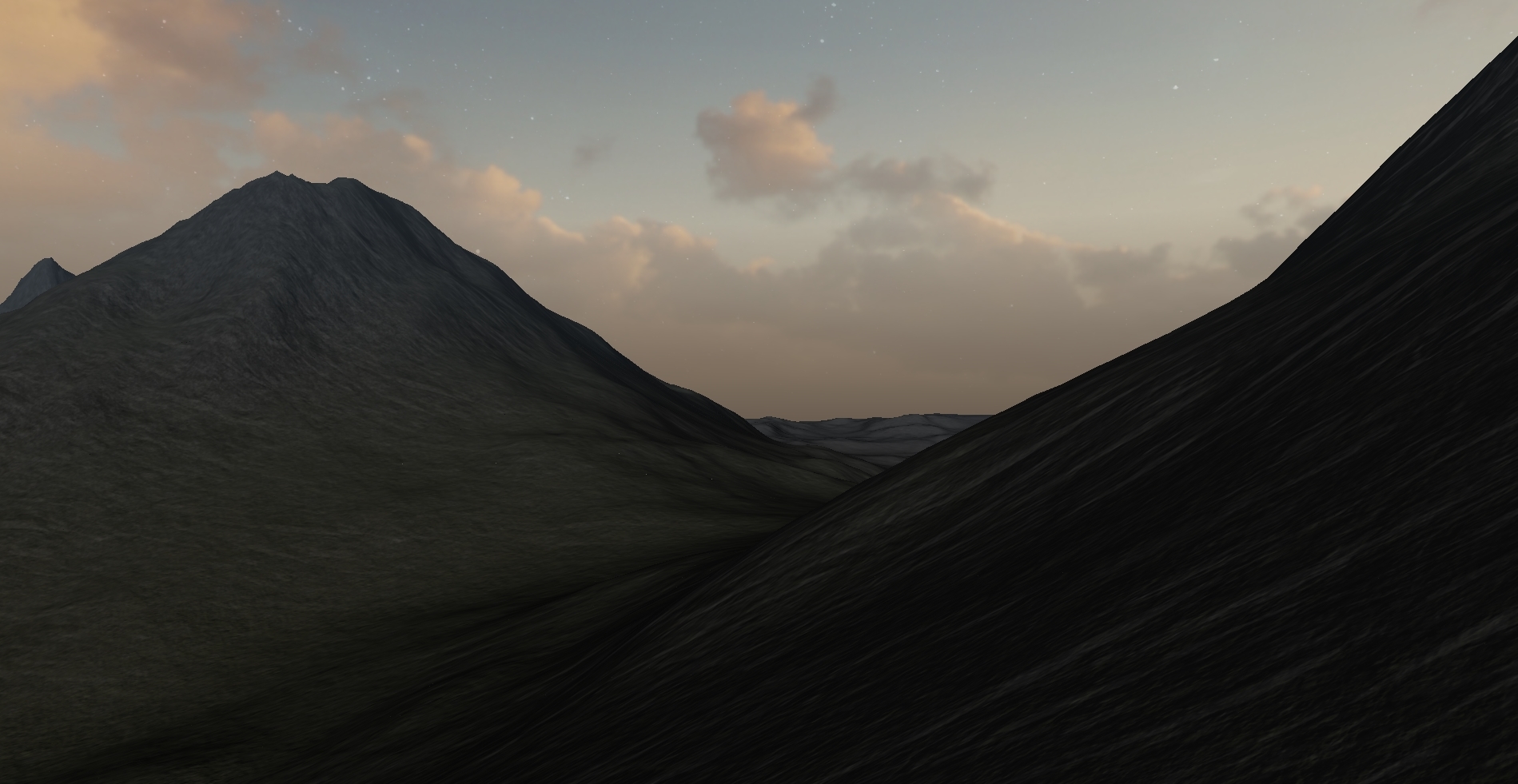
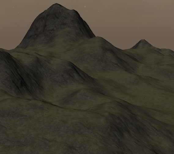
As a final project for the Spring 2018 section of Graphics 471, I created a procedural terrain. The goal for this terrain was for it to be as large and realistic as possible. Because of this, I put a lot of emphasis on the quality of the environment and the performance of the shaders. Additionally, the terrain has geographically and environmentally different regions that blend together as the camera flies through the environment.
Generating the Terrain Heightmap
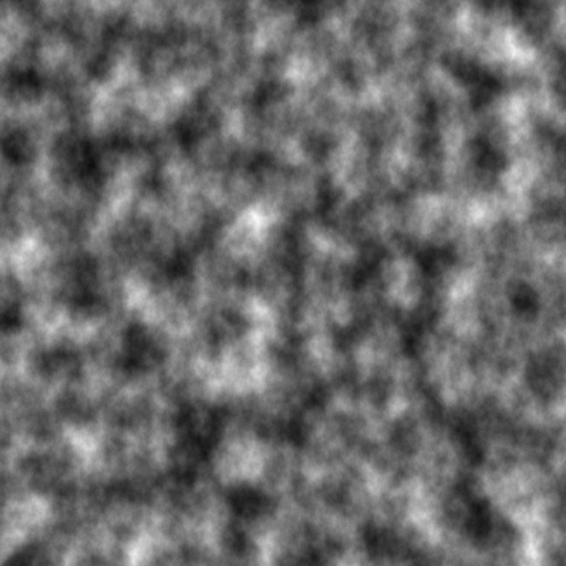
The heightmap for the terrain in this project is generated using a perlin noise function, which is a type of pseudorandom noise that produces gradual increases and decreases in output as the input is increased and decreased. This behavior is what makes perlin noise useful for generating terrains - it's random, but not too random.
When one or more "layers" of these noise maps are combined, they can create a hierarchy of scale. The lower level map(s) can define the major geographical features like mountains and vallies, and the hhigher level maps provide the smaller details like rocks and bumps.
Noise with a Terrain Mesh
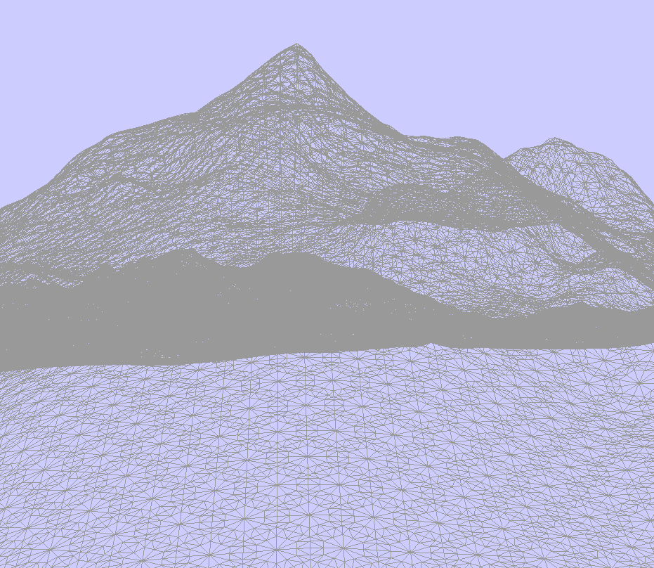
So how is all of this translated into a mesh of verticies that OpenGL can interpret? Firstly, the only vertex data that needs to be provided to the shader is a grid of NxN squares. The greater the "resolution" of this grid, the more detail can be present in the terrain (exluding tessellation, which is described below). Keep in mind, all of the Y values of this mesh are 0 at this point, so the terrain is completely flat.
Because we want this terrain to be infinitely procedural, we have to calculate the heights of the mesh on the fly in the vertex (or tessellation) shader and not on the CPU when we first generate the mesh. Below is an example of how to do this in the shader:
float hash(float n) {
    return fract(sin(n) * 753.5453123);
}

float snoise(vec3 x)
{
	vec3 p = floor(x);
	vec3 f = fract(x);
	f = f * f * (3.0f - (2.0f * f));

	float n = p.x + p.y * 157.0f + 113.0f * p.z;
	return mix(mix(mix(hash(n + 0.0f), hash(n + 1.0f), f.x),
		mix(hash(n + 157.0f), hash(n + 158.0f), f.x), f.y),
		mix(mix(hash(n + 113.0f), hash(n + 114.0f), f.x),
			mix(hash(n + 270.0f), hash(n + 271.0f), f.x), f.y), f.z);
}

float noise(vec3 position, int octaves, float frequency, float persistence) {
	float total = 0.0f;
	float maxAmplitude = 0.0f;
	float amplitude = 1.0f;
	for (int i = 0; i < octaves; i++) {
		total += snoise(position * frequency) * amplitude;
		frequency *= 2.0f;
		maxAmplitude += amplitude;
		amplitude *= persistence;
	}
	return total / maxAmplitude;
}

void main() {
	float height = noise(pos.xyz, 10, 0.002, 0.3);
	pos.y = height;
	vertex_pos = pos.xyz;
	gl_Position = P * V * pos;
}
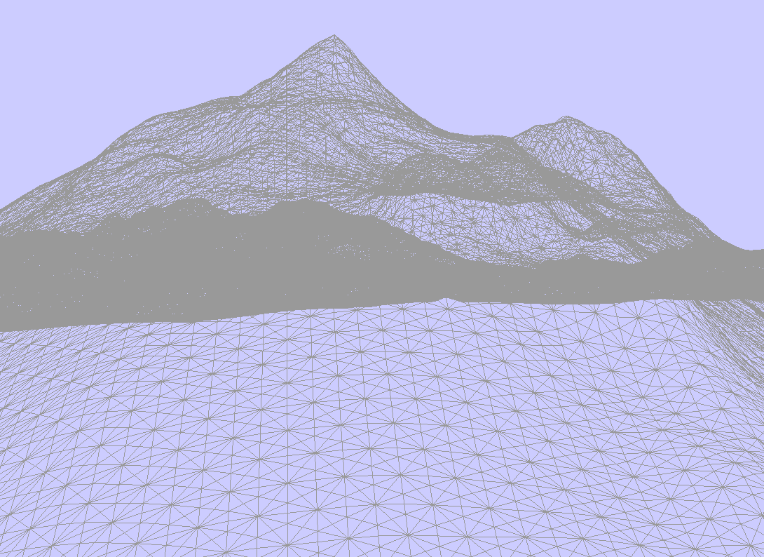
Tessellation
One quick way to improve the quality of the mesh, as well as performance, is to utilize tessellation. The ideas behind tessellation are:
- More vertices in an object = more vertices to process = lower performance
- Objects far in the distance don't need to have as many vertices because we couldn't tell if they did
- We can subdivide the triangles in a mesh, depending on how close or far it is
By sacrificing the quality of distant elements (which in this case is the majority of the terrain), performance and the quality of nearby elements are improved vastly. OpenGL handles most of the work when implementing tessellation, but it requires the use of two additional shaders: a tessellation control shader and a tessellation evaluation shader. The control shader determines the factor by which the triangles in a mesh are subdivided, thereby controlling the overall quality of the mesh. The evaluation shader processes the newly generated vertices, and applies any displacement necessary.
Considering the Y values of the terrain mesh aren't stored, rather calculated as they're needed, tessellation is super easy to implement. Instead of getting our heights from the noise function in the vertex shader, we can do it in the tessellation evaluation shader. Becauase perlin noise has a sort of natural interpolation between heights, it doesn't matter which point exactly is calculated as long as it's close enough to its neighbors to not create a huge jump in height.
The only thing to do after moving the calculation of the heights to the tessellation evaluation shader is to determine the tessellation factor for the control shader. Because, we want the portion of the mesh closest to the camera to have the greatest number of vertices, the tessellation factor has to be proportional (in some way) to the distance between the camera and the vertex being processed:
float calculateTessFactLinear() {
	float df = meshsize * resolution;
	float dist = df - length(campos.xz + vertex_pos[gl_InvocationID].xz);
	dist /= df;
	dist = pow(dist, 5); // roughly controls proportionality of distance to tessellation factor

	float tessfact = dist * 5; // roughly controls the range of the tessellation factor
	tessfact = max(1, tessfact);
	return tessfact;
}

void main(void)
{
	float tessfact = calculateTessFactLinear();

	gl_TessLevelInner[0] = tessfact;
	gl_TessLevelInner[1] = tessfact;
	gl_TessLevelOuter[0] = tessfact;
	gl_TessLevelOuter[1] = tessfact;
	gl_TessLevelOuter[2] = tessfact;

	gl_out[gl_InvocationID].gl_Position = gl_in[gl_InvocationID].gl_Position;
	TE_vertex_tex[gl_InvocationID] = vertex_tex[gl_InvocationID];
}
Calculating Normals
For me, this was one of the more challenging roadblocks in this project. Because the vertex data isn't pre-computed, the normals can't be calculated during initialization like they can when loading in a pre-generated heightmap or object file, so I had to do this along side the height calculation in the tessellation evaluation shader.
Since the positions of the neighboring vertices aren't known, I created the needed triangle using two points that were slightly offset from the vertex being processed. Once I got the heights for those vertices using the same perlin noise function as before, I was able to compute an approximate normal for that vertex in the evaluation shader and pass it to the fragment shader. It's worth noting that I also calculate the tangent and bitangent vectors at that same stage (they're needed for bump mapping later on).
vec3 calculateNormal(vec3 p1) {
	float delta = 0.5f;

	vec3 p2 = (p1 + vec3(delta, 0.0f, 0.0f)) * vec3(1.0f, 0.0f, 1.0f);
	vec3 p3 = (p1 + vec3(0.0f, 0.0f, -delta)) * vec3(1.0f, 0.0f, 1.0f);

	p2.y = getHeight(p2);
	p3.y = getHeight(p3);

	vec3 u = p2 - p1;
	vec3 v = p3 - p1;

	vec3 normal = vec3(0.0f);
	normal.x = (u.y * v.z) - (u.z * v.y);
	normal.y = (u.z * v.x) - (u.x * v.z);
	normal.z = (u.x * v.y) - (u.y * v.x);

	return normalize(normal);
}
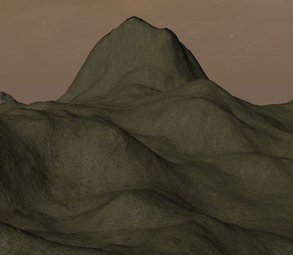
Applying Textures & Details
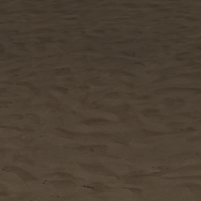
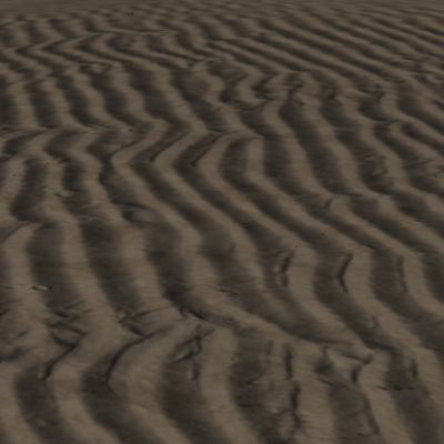
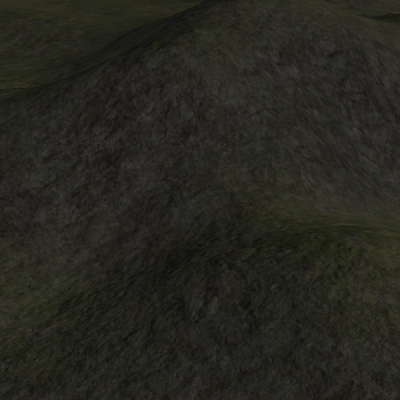
With the geometry in place, we can start throwing some textures on the terrain. The basics are pretty simple- just pass a repeating texture with coordinates through to the height shader. However, without any extra work, the textures create an unpleasant "tiling" effect that comes from the small artifacts within the texture that become obvious when repeated over and over.
The most infallible way to fix this would be to use a massive texture with no repeating elements that is the size of the visible area of the mesh (good luck). A more realistic approach, though, is to blend two or more layers of the same texture that are each scaled or rotated differently, and using that as the texture that is applied to the mesh. This method works pretty well, but it has the drawback of the tradeoff between texture detail and tiling artifacts. In other words, blending more means less tiling but a blurrier texture, and blending less means more detail but also more obvious tiling I found that using three "layers" of textures was a pretty good sweet spot.
vec3 blendRGB(vec3 rgbA, vec3 rgbB, vec3 rgbC, float alpha) {
	return (rgbA * alpha) + (rgbB * alpha) + (rgbC * alpha);
}

vec4 grassLower = vec4(texture(grassSampler, texcoords * 10 + 5, 0).rgb * 1, 1.0);
vec4 grassMid = vec4(texture(grassSampler, texcoords * 15 + 20, 0).rgb * 1, 1.0);
vec4 grassUpper = vec4(texture(grassSampler, texcoords * 20 + 30, 0).rgb * 1, 1.0);
vec4 grassDetiled = vec4(blendRGB(grassLower.rgb, grassMid.rgb, grassUpper.rgb, 0.33), 1.0);
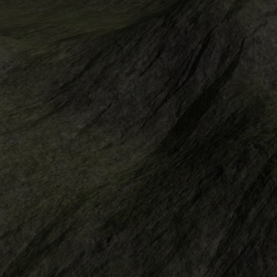
Blending in Cliffs
The detiling of the base texture helps a bit, but the terrain still looks a bit flat. It's unrealistic to have grass growing on very steep surfaces, so I blended in a cliff texture where the mesh was steep to help mix things up a bit. To do this, we need to know the "slope" of the plane that contains a certain vertex. Luckily, this is pretty easily done using just the Y values of the normals that were calculated in the tessellation evaluation shader.
Another nice touch is to decrease the strength of the cliff blending at lower elevations. We just repeat the previous step, but instead we mix using the Y value of the vertex position.
// Blend cliff texture using the y component of the normal
vec3 cliffMixed = mix(cliffDiffused, color.rgb, pow(vertex_norm.y, 5));
// Reduce cliffs at lower vertex Y values
color.rgb = mix(color.rgb, cliffMixed, min(vertex_pos.y / 0.7f, 1));
main.cpp or wherever textures are loaded
// Grass texture
str = resourceDirectory + "/grass.jpg";
strcpy(filepath, str.c_str());
data = stbi_load(filepath, &width, &height, &channels, 4);
glGenTextures(1, &GrassTexture);
glActiveTexture(GL_TEXTURE0);
glBindTexture(GL_TEXTURE_2D, GrassTexture);
glTexImage2D(GL_TEXTURE_2D, 0, GL_RGBA8, width, height, 0, GL_RGBA, GL_UNSIGNED_BYTE, data);
glTexParameteri(GL_TEXTURE_2D, GL_TEXTURE_WRAP_S, GL_REPEAT);
glTexParameteri(GL_TEXTURE_2D, GL_TEXTURE_WRAP_T, GL_REPEAT);
glTexParameteri(GL_TEXTURE_2D, GL_TEXTURE_MIN_FILTER, GL_LINEAR_MIPMAP_LINEAR);
glTexParameteri(GL_TEXTURE_2D, GL_TEXTURE_MAG_FILTER, GL_LINEAR);
//glTexParameteri(GL_TEXTURE_2D, GL_TEXTURE_MAX_LEVEL, 3);
glGenerateMipmap(GL_TEXTURE_2D);
Generating Mipmaps
The last thing to do is a performance optimization using mipmaps. Just like with tessellation, we don't need the quality of distant textures to be as good as those nearby. Luckily, OpenGL handles this almost automatically, and it's only necessary to add a couple lines of code.
On the left code block where I load the grass texture, I added the texture parameter GL_LINEAR_MIPMAP_LINEAR, as well as the final line glGenerateMipmap(GL_TEXTURE_2D);
to instruct OpenGL to generate and use mipmaps for that texture. Optionally, you can include another parameter, GL_TEXTURE_MAX_LEVEL to specify the minimum level of detail
allowable.
Lighting & Normal Maps
Another touch that makes the environment feel much more realistic is the use of lighting and bump maps for textures. Bump maps are a tool that use lighting concepts to add additional detail to textures, and they look great when combined with the day-night cycle I've implemented.
A normal map is essentially a copy of a texture, but each pixel represents the normal vector of the texture at that point. This causes the texture to have a three-dimensional
appearance even though no additional vertices are added to the mesh. In my implementation, I blend together the normal map of the texture (combined with scene lighting) with the
detiled texture itself, and by doing this, I can have distinct bump maps and details for each texture. The getTextureDiffuse function in my fragment shader takes in the
normal map for a texture and the texture itself, and it blends the two, applies lighting, and returns the "diffused" texture.
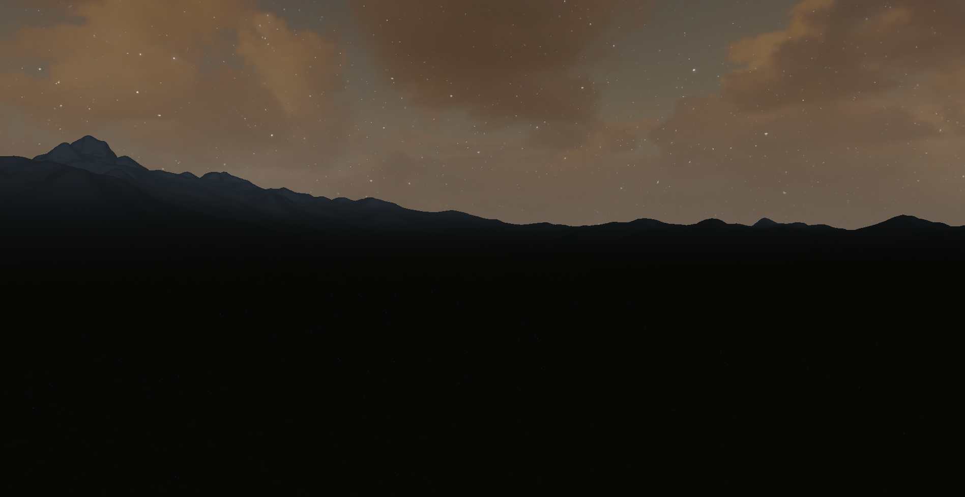
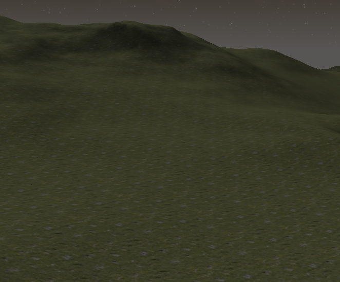
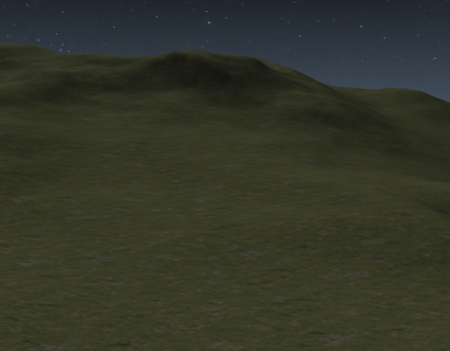
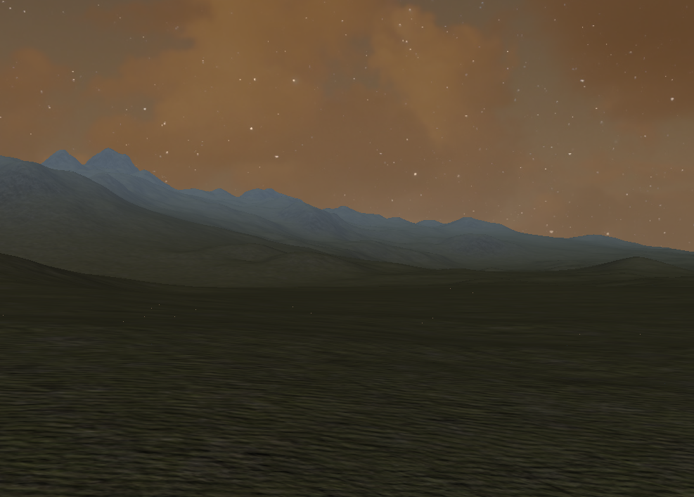
Simulating Day & Night
I decided that there were three important components when trying to simulate a realistic transition between day and night:
- An increase and decrease in lighting as time increases
- The movement and strength of shadows as the sun changes travels across the sky
- Separate skybox textures that blend with each other relative to time
The first two points can be tackled at the same time. When calculating the diffuse lighting for a texture and the scene as a whole, I can specify that the Y and Z positions of simulated sun should be the sine and cosine of the current time (which increases by some factor each render call). Because the diffuse lighting factor for a given pixel is just the dot product between the direction of the sun and the bump map value of the texture at that point, both the intensity and angle of the lighting are both calculated at that point.
As for the skybox, I picked two textures- one each for day and night. In the fragment shader for the skybox, I mixed the two textures together with the alpha factor being the sine of the current time, plus a small offset to make sure the skybox texture was aligned with the lighting on the terrain. Additionally, I further mixed the given sky texture with a light orange tint with twice the frequency of the sky itself. This simulates a nice sunrise/sunset effect when the sky transitions from day to night and vice versa.
float oscillate(float t, float min, float max) {
	float halfRange = (max - min) / 2;
	return (min + halfRange) + (sin(t + 5.4) * halfRange);
}

void main() {
	vec4 tcol = texture(dayTexSampler, vertex_tex);
	vec4 ncol = texture(nightTexSampler, vertex_tex);

	color.rgb = mix(tcol.rgb, ncol.rgb, oscillate(time, 0.1f, 1.0f));
	color.rgb = mix(color.rgb, vec3(1.0, 0.6, 0.2), oscillate(time * 2, 0.0f, 0.3f));

	color.a = 1;
}
vec3 getTextureDiffuse(vec3 normalMap, vec3 tex) {
	float sTime = sin(time);
	float cTime = cos(time);

	vec3 cliffNormalMap = normalMap;
	cliffNormalMap = (cliffNormalMap - vec3(0.5, 0.5, 0.5)) * 2;
	vec3 bumpNormal = (cliffNormalMap.x * vertex_tan) + (cliffNormalMap.y * vertex_bi) + (cliffNormalMap.z * vertex_norm);	//rotate normal into tangent space
	bumpNormal = normalize(bumpNormal);

	// Diffuse lighting
	vec3 distance = vec3(0, cTime * 1.1, sTime * 1.1);
	float diffuse = dot(bumpNormal, distance);
	return tex * max(0.1, diffuse * 1.0);
}
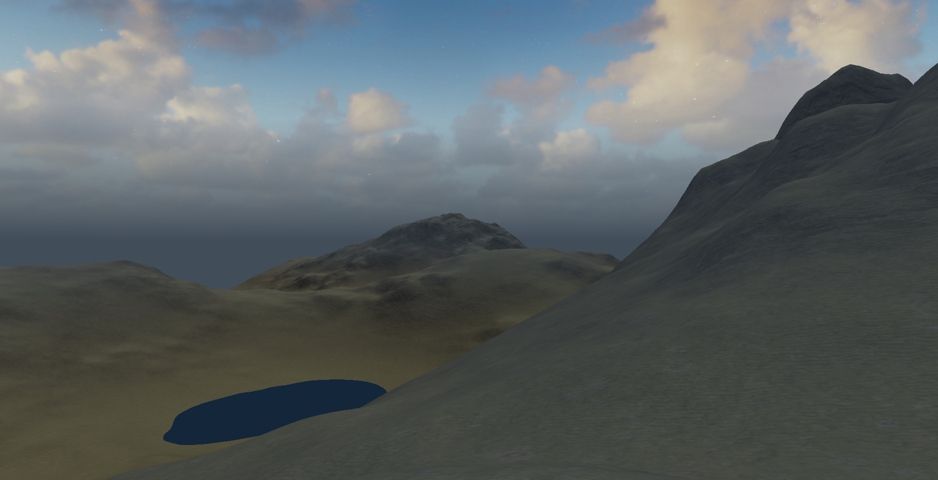
Height-based Fog
One last thing to improve the ambiance of the scene is to implement some sort of fog to improve the harsh cutoff look as new terrain becomes visible. Additionally, a height factor can be included so that either higher or lower points of the terrain have more or less fog. Additionally, I blended the color of the fog with the skybox near the horizon, which makes for less of a harsh distinction between distant terrain and the sky box, as well as a cool glow effect.
vec3 applyFog(vec3 rgb, float distance, float density, vec3 rayOri, vec3 rayDir) {
	float c = 0.1f;
	float fogAmount = c * exp(-rayOri.y * density) * min((1.0 - exp(-distance * rayDir.y * density)) / rayDir.y, 1.0);
	vec3  fogColor = vec3(0.5, 0.6, 0.7);
	return mix(rgb, fogColor, fogAmount);
}

void main()
{
    ...

    color.rgb = applyFog(color.rgb, length(campos - vertex_pos), 0.01f, campos, normalize(campos - vertex_pos)) * max(cTime, 0.2);
    color.a = 1;
}
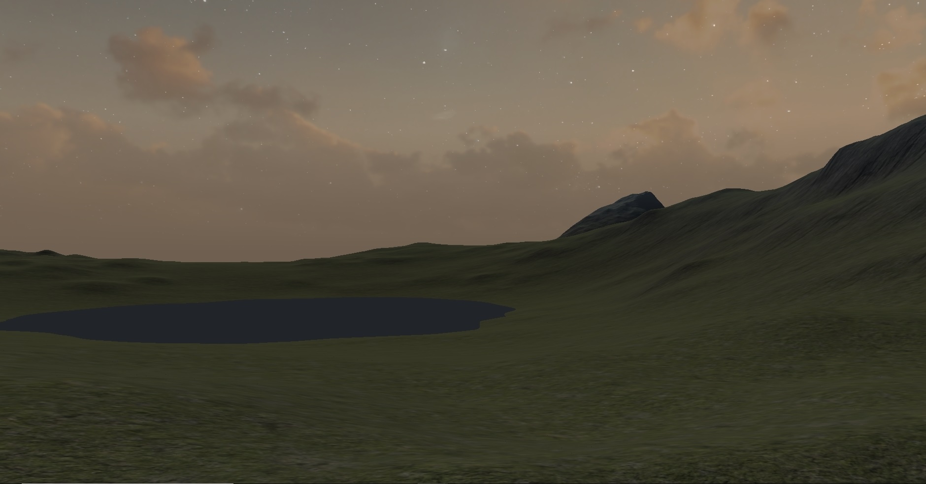
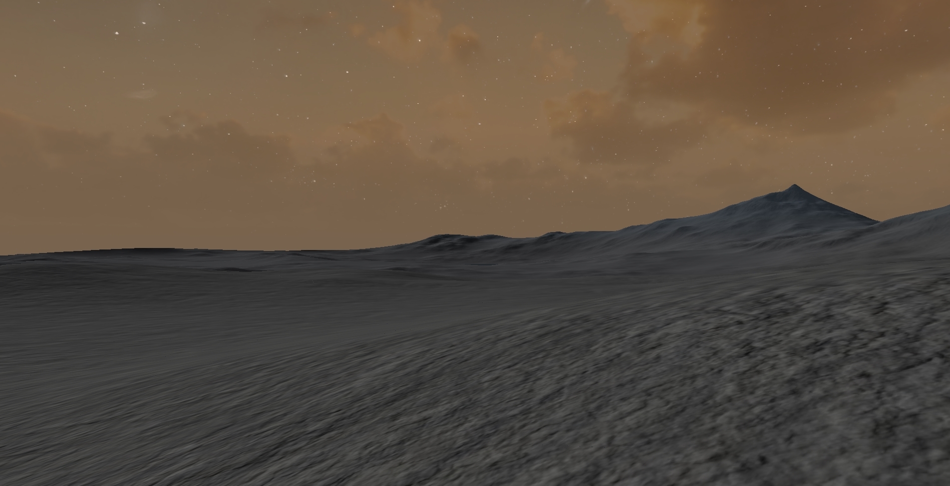
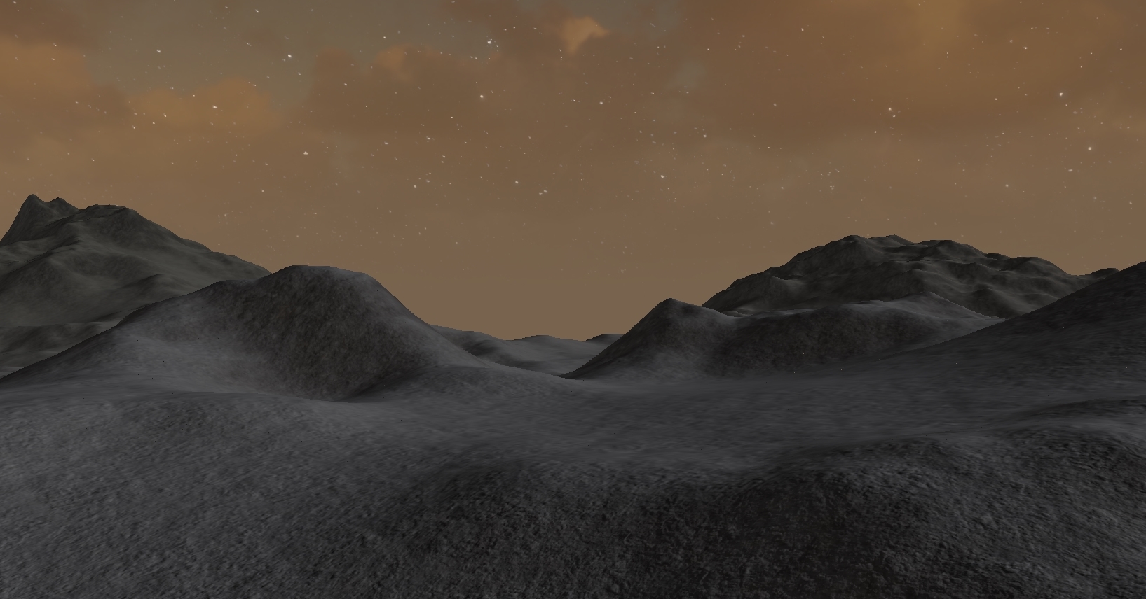
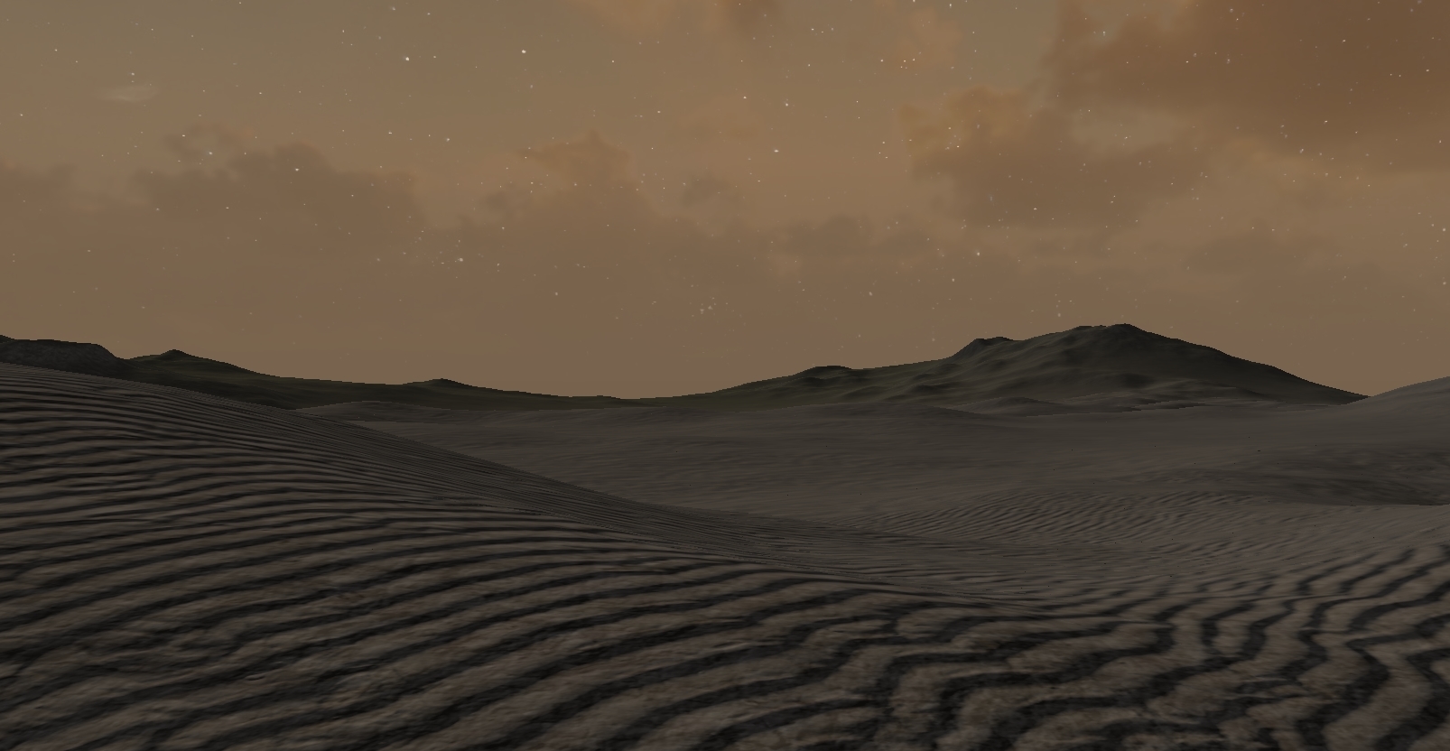
Regional geography
The last thing to do with the terrain is to incorporate different regions. These regions will have variant geography (ex. hilly vs mountainous) and temperance (snowy vs grassy). The way I did this was with three separate perlin noise maps.
For the geography, the noise values at each vertex determine the strength of the features in the actual getHeight function in the evaluation shader. I created a set of
minimum and maximum values for things in the noise function like frequency, persistence, Y translation, and scale, and I interpolate between them based on the height of the geography
noise.
By doing this, I can ensure that certain regions of the terrain will be flat, smooth, and low whereas others will have more intensity, ruggedness, and height. Beyond that, the scale of and distance between these regions can almost directly be controlled with the frequency parameter of the biome height nosie function. A lower frequency will result in more expansive regions, and a higher frequency will result in features being closer together.
Temperature and Humidity
After figuring out the mesh features, I needed a way to blend the various textures in a way that made sense. To do this, I implemented two control variables: temperature and humidity. Both variables are pulled from the same noise function with different parameters and position offsets, and they control the blending ratio of snow to sand/grass and grass to sand. In other words, a region with higher humidity will have more grass compared to sand, and a region with a lower temperature will have more snow than either.
float getHeight(vec3 pos) {

	float dist = length(pos);

	int biomeOctaves = 3;
	float biomeFreq = 0.01f;
	float biomePers = 0.3f;
	float biomePreIntensity = 2;
	float biomePower = 2;
	float biomePostIntensity = 3;
	float biomeTranslate = 0.0f;

	float biomeHeight = pow(noise(pos.xyz + vec3(100.0), 2, 0.01f, 0.1f), 2) * 1;
	biomeHeight = clamp(biomeHeight, 0, 1);

	colorO = biomeHeight;

	int baseOctaves = 11;
	float baseFreq = 0.05;
	float basePers = mix(0.2, 0.2f, biomeHeight);
	float basePreIntensity = mix(0.7, 0.7, biomeHeight);
	float power = 2;
	float basePostIntensity = mix(3, 40, biomeHeight);
	float translate = mix(0, 50, biomeHeight);


	int heightOctaves = 11;
	float heightFreq = 0.1;
	float heightPers = mix(0.3, 0.4, biomeHeight);
	float heightPreIntensity = mix(0.8, 1.5, biomeHeight);


	float baseheight = noise(pos.xzy, baseOctaves, baseFreq, basePers) * basePreIntensity;
	float height = noise(pos.xzy, heightOctaves, heightFreq, heightPers) * heightPreIntensity;
	baseheight = pow(baseheight, power) * basePostIntensity;
	height = baseheight * height + translate;

	return height;
}
Future Work
This project was a bunch of fun to work on, and if I were to continue improving it I'd like to implement a number of other features:
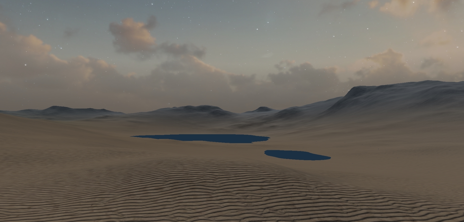
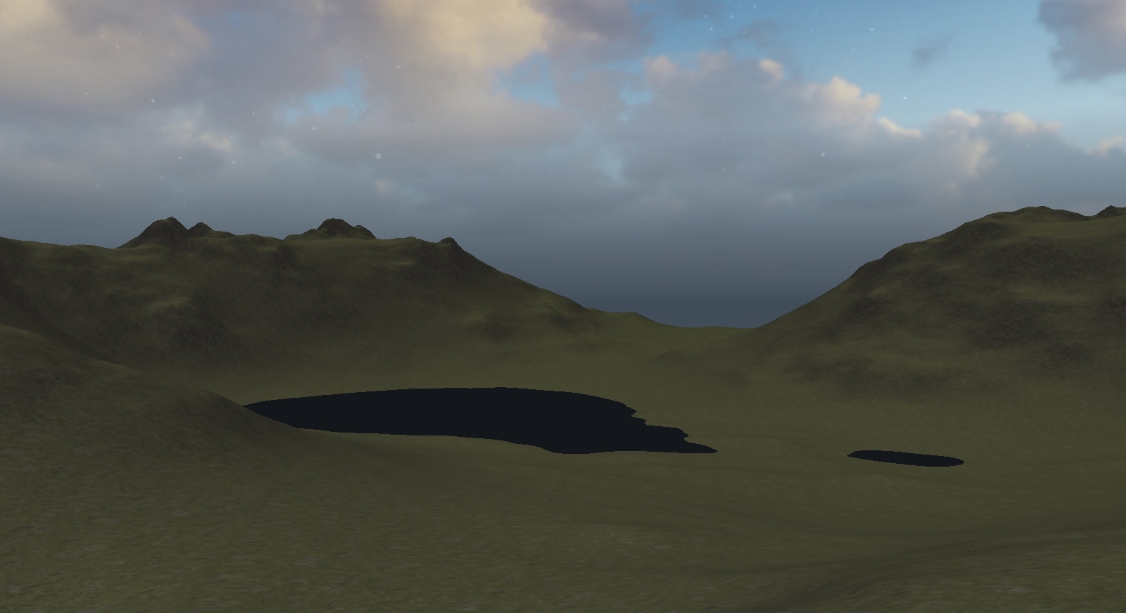
- More detailed water and reflection (right now, the water is just a giant, 6-vertex mesh with a single color output in the fragment shader)
- Lower LOD outer terrain meshes: Render a set of lower resolution terrain meshes around the one in which the camera is positioned
- Additional environmental effects like weather, particle effects, a visible sun
- Better camera controls
- More performance optimizations like frustum culling and rendering in chunks
- Larger selection of textures and more varied regions