
Introduction
For this project, I was tasked with creating an atmosphere that could sit on a real scale planet. To do so, I used Rayleigh and Mie scattering to approximate the colors produced from light passing through the atmosphere. Rayleigh scattering scatters short wavelength light more than longer wavelengths, so blue light is scattered more by the atmosphere than red light, causing the sky to appear blue. Mie scattering scatters all wavelengths equally, and is caused by pollutants, dust, mist, and other dense particles in the air.
My implementation of atmospheric scattering is a pre-pass ray tracing solution. I generate rays through a quad and calculate Rayleigh and Mie scattering values alogn their paths. This is currently done as a pre-pass because it was easier to not use the depth buffer when drawing the atmosphere on a quad, however this solution can be adapted as a post processing effect by accounting for the depth buffer when drawing the quad.
In this article, I will discuss what atmospheric scattering is, what my code does, and how the inputs can be manipulated to vary the appearance of the atmosphere. I will also discuss what I did in the project and what can be improved upon later.
For my implementation, there are four interesting functions: DrawAtmosphere, SetAtmosphereView, CalcualteFrustumFarBounds, and atmosphere.
What Is Atmospheric Scattering
Atmospheric scattering is a model for how light scatters in the atmosphere, creating the colors that we are used to seeing. My goal here is not to explain how all of these equations and concepts work, but rather how to use them to generate the desired effects. More information on how atmospheric scattering works can be found HERE.
This implementation of atmospheric scattering is a raytracing technique used in this real-time solution by intersecting rays with the outer edge of the atmosphere and sampling along the path from the camera to the intersection point, calculating the Rayleigh and Mie values at each point. We assume in this model that the planet is a perfect sphere and nothing other than the planet intersects the rays as they travel through the atmosphere.
Translating A Perspective Matrix For Raycasting
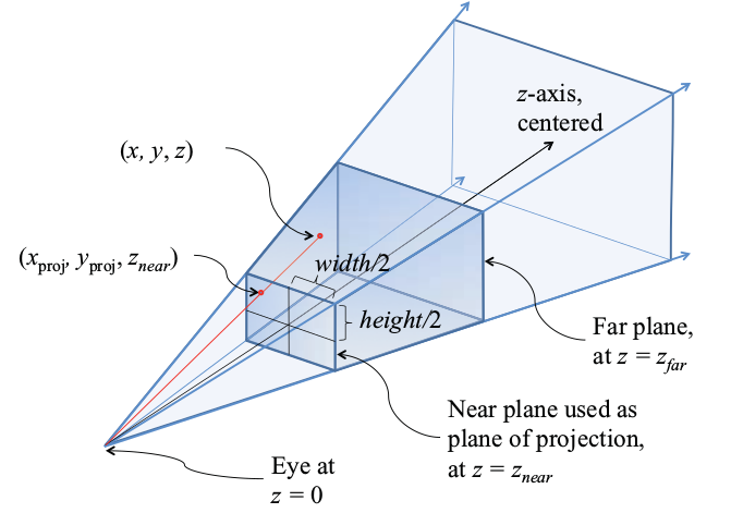
For my model, the atmosphere is drawn on a quad. The quad is placed at the far plane of the perspective matrix. In the fragment shader, the fragment locations are used as the target for rays, determining which direction to trace along. The quad is placed to match the far plane of the perspective matrix to easily translate the perspective space used by the camera to the perspective space for raytracing.
void DrawAtmosphere(const glm::mat4 & P)
{
	// Draw the sky
	progAtmos->bind();

	glm::mat4 V = SetAtmosphereView();
	//This is positioning the quad at the near plane of the perspective view frustum
	glm::mat4 M = CalcualteFrustumFarBounds(mycam.getFOV(), mycam.getFarDist(), mycam.getAspect());

	//send the matrices to the shaders
	glUniformMatrix4fv(progAtmos->getUniform("M"), 1, GL_FALSE, &M[0][0]);
	glUniformMatrix4fv(progAtmos->getUniform("V"), 1, GL_FALSE, &V[0][0]);
	glUniformMatrix4fv(progAtmos->getUniform("P"), 1, GL_FALSE, &P[0][0]);
	glUniform3fv(progAtmos->getUniform("campos"), 1, &mycam.getLocation()[0]);
	glUniform3fv(progAtmos->getUniform("uSunPos"), 1, &sun.position[0]);

	glDisable(GL_DEPTH_TEST);
	atmosQuad->draw(progAtmos);

	glEnable(GL_DEPTH_TEST);

	progAtmos->unbind();
}

// This takes a unit quad and places it at the far plane
//      of the view frustum with the same dimensions
// @fovy The field of view in the y direction of the camera.
// @far The distance to the far plane from the camera.
// @aspect The aspect ratio of the camera.
glm::mat4 CalcualteFrustumFarBounds(float fovy, float far, float aspect) {
	// The length of the hypotenuse of the triangle defined by the camera, the middle of the atmosphere quad, and the top of the atmosphere quad.
	float hypot = far / sin(fovy * 2 * pi / 360.0f);
	// The angle between the hypotenuse and atmosphere quad.
	float angle = 90.0f - fovy;
	// The length of the quad from center to top.
	float side = sin(angle * 2 * pi / 360.0f) * hypot;

	auto S = glm::scale(glm::mat4(1.0f), glm::vec3(side * aspect, side, 1.0f));
	auto T = glm::translate(glm::mat4(1.0f), glm::vec3(0.0f, 0.0f, far));
	return S * T;
}

// Returns the rotation matrix to match the camera's rotation for the atmosphere plane
// Assumes two degrees of freedom for the camera, pitch and yaw. Roll is not currently supported.
glm::mat4 SetAtmosphereView()
{
	auto R = glm::rotate(glm::mat4(1.0f), -mycam.getTheta(), glm::vec3(0.0f, 1.0f, 0.0f));
	R *= glm::rotate(glm::mat4(1.0f), mycam.getPhi(), glm::vec3(1.0f, 0.0f, 0.0f));
	return R;
}
DrawAtmosphere
DrawAtmosphere() is a standard draw call for a gl program, except that the depth test must be turned off for the draw call. This is explained further in the CalculateFrustamFarBounds description. Because we turn of the depth buffer check, the atmosphere must be drawn first with the current model. This could be changed by importing a depth buffer into the shader and only drawing if the pixel has no depth information, or by correctly transforming the gl_Position of the fragment in the vertex shader.
SetAtmosphereView
SetAtmosphereView() returns the view matrix for the atmosphere quad. This function takes the direction the camera is facing and makes the quad appear in the center of the camera’s direction. This function assumes that the quad is centered along the positive z-axis, and that the quad has been scaled and translated to match the far plane for the camera’s perspective matrix. Once the quad is in position, the view matrix rotates the quad by the yaw angle Theta about the y-axis, and the pitch angle Phi about the x-axis. I did not support roll with this camera, but adding support for roll should be as simple as adding a rotation about the z-axis by the roll angle. This method was used primarily because the camera I was using already had the values for theta and Phi calculated, so grabbing those and using them to calculate the camera’s direction seemed to be a simple solution.
CalculateFrustumFarBounds
CalculateFrustumFarBounds() takes in information from the camera about the perspective matrix, then does some trigonometry to place the atmosphere quad at the far plane of the perspective matrix, with scaled width and height to match the bounds of the frustum’s far plane. This function is key because it defines the scale and location of the quad that all of the rays are defined by.
#version 410 core

out vec4 color;
in vec4 fragPos;
uniform vec3 campos;
uniform vec3 uSunPos;

#define PI 3.141592
#define iSteps 16
#define jSteps 8
#define planetRadius 6372e3

vec2 rsi(vec3 r0, vec3 rd, float sr) {
    // ray-sphere intersection that assumes
    // the sphere is centered at the origin.
    // No intersection when result.x > result.y
    float a = dot(rd, rd);
    float b = 2.0 * dot(rd, r0);
    float c = dot(r0, r0) - (sr * sr);
    float d = (b*b) - 4.0*a*c;
    if (d < 0.0) return vec2(1e5,-1e5);
    return vec2(
        (-b - sqrt(d))/(2.0*a),
        (-b + sqrt(d))/(2.0*a)
    );
}

vec3 atmosphere(vec3 r, vec3 r0, vec3 pSun, float iSun, float rPlanet, float rAtmos, vec3 kRlh, float kMie, float shRlh, float shMie, float g) {
    // Normalize the sun and view directions.
    pSun = normalize(pSun);
    r = normalize(r);

    // Calculate the step size of the primary ray.
    vec2 p = rsi(r0, r, rAtmos);
    if (p.x > p.y) return vec3(0,0,0);
    p.y = min(p.y, rsi(r0, r, rPlanet).x);
    float iStepSize = (p.y - p.x) / float(iSteps);

    // Initialize the primary ray time.
    float iTime = 0.0;

    // Initialize accumulators for Rayleigh and Mie scattering.
    vec3 totalRlh = vec3(0,0,0);
    vec3 totalMie = vec3(0,0,0);

    // Initialize optical depth accumulators for the primary ray.
    float iOdRlh = 0.0;
    float iOdMie = 0.0;

    // Calculate the Rayleigh and Mie phases.
    float mu = dot(r, pSun);
    float mumu = mu * mu;
    float gg = g * g;
    float pRlh = 3.0 / (16.0 * PI) * (1.0 + mumu);
    float pMie = 3.0 / (8.0 * PI) * ((1.0 - gg) * (mumu + 1.0)) / (pow(1.0 + gg - 2.0 * mu * g, 1.5) * (2.0 + gg));

    // Sample the primary ray.
    for (int i = 0; i < iSteps; i++) {

        // Calculate the primary ray sample position.
        vec3 iPos = r0 + r * (iTime + iStepSize * 0.5);

        // Calculate the height of the sample.
        float iHeight = length(iPos) - rPlanet;

        // Calculate the optical depth of the Rayleigh and Mie scattering for this step.
        float odStepRlh = exp(-iHeight / shRlh) * iStepSize;
        float odStepMie = exp(-iHeight / shMie) * iStepSize;

        // Accumulate optical depth.
        iOdRlh += odStepRlh;
        iOdMie += odStepMie;

        // Calculate the step size of the secondary ray.
        float jStepSize = rsi(iPos, pSun, rAtmos).y / float(jSteps);

        // Initialize the secondary ray time.
        float jTime = 0.0;

        // Initialize optical depth accumulators for the secondary ray.
        float jOdRlh = 0.0;
        float jOdMie = 0.0;

        // Sample the secondary ray.
        for (int j = 0; j < jSteps; j++) {

            // Calculate the secondary ray sample position.
            vec3 jPos = iPos + pSun * (jTime + jStepSize * 0.5);

            // Calculate the height of the sample.
            float jHeight = length(jPos) - rPlanet;

            // Accumulate the optical depth.
            jOdRlh += exp(-jHeight / shRlh) * jStepSize;
            jOdMie += exp(-jHeight / shMie) * jStepSize;

            // Increment the secondary ray time.
            jTime += jStepSize;
        }

        // Calculate attenuation.
        vec3 attn = exp(-(kMie * (iOdMie + jOdMie) + kRlh * (iOdRlh + jOdRlh)));

        // Accumulate scattering.
        totalRlh += odStepRlh * attn;
        totalMie += odStepMie * attn;

        // Increment the primary ray time.
        iTime += iStepSize;

    }

    // Calculate and return the final color.
    return iSun * (pRlh * kRlh * totalRlh + pMie * kMie * totalMie);
}


void main() {
    vec3 col = atmosphere(
        normalize(vec3(fragPos)),               // normalized ray direction
        vec3(0,planetRadius,0) + campos,        // ray origin
        uSunPos,                                // position of the sun
        22.0,                                   // intensity of the sun
        planetRadius,                           // radius of the planet in meters
        planetRadius + 100e3,                   // radius of the atmosphere in meters
        vec3(5.5e-6, 13.0e-6, 22.4e-6),         // Rayleigh scattering coefficient
        21e-6,                                  // Mie scattering coefficient
        8e3,                                    // Rayleigh scale height
        1.2e3,                                  // Mie scale height
        0.758                                   // Mie preferred scattering direction
    );

    // Apply exposure.
    col = 1.0 - exp(-1.0 * col);

    color = vec4(col, 1);
}
Atmosphere
atmosphere() takes in information about the atmosphere, the planet, the star, and the camera, and returns the color seen in the given direction for the atmosphere. There are 11 arguments given to the atmosphere function, and each is covered below:
Ray Direction (normalized)
The direction of the ray is calculated by taking the fragment position and subtracting the eye location, which we have defined to always be (0,0,0) to simplify this to just the fragment position.
Ray Origin
This is seperate from the ray direction calculation.For my camera, the north pole of the planet is located at (0,0,0), so the camera must be offset by the planet radius here in order to view the atmosphere from the planet’s surface.
Sun Position
The position of the sun.
Planet radius (in meters)
The radius of the planet in meters. This should match the size of the planet you are rendering. This value is currently defined in both the shader and in main.cpp. It should be defined once in main.cpp or by a planet object, then passed into the shader.
Atmosphere radius (in meters)
The radius to the outer edge of the atmosphere. This number should be larger than the planet’s radius or else no atmosphere will be outside of the planet.
Sun intensity
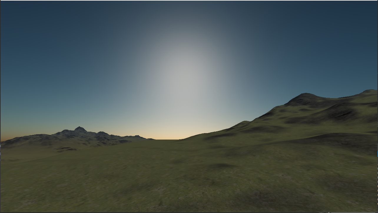
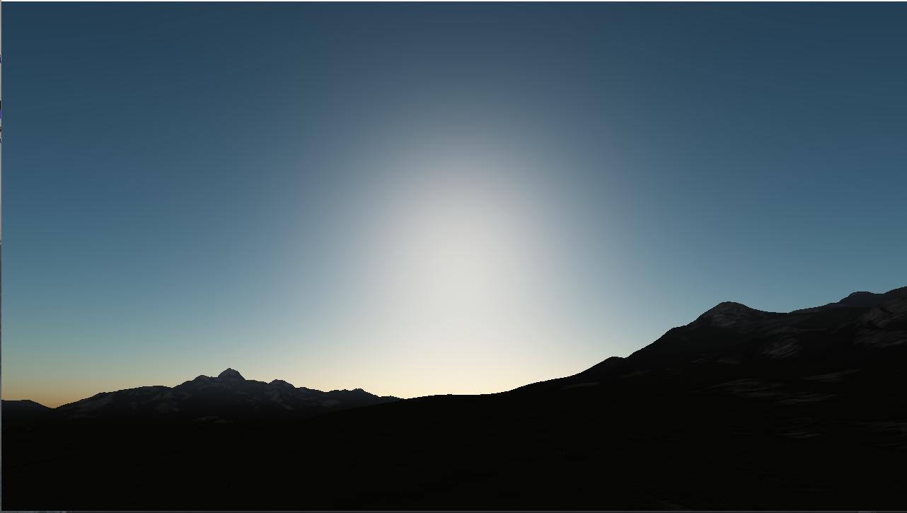
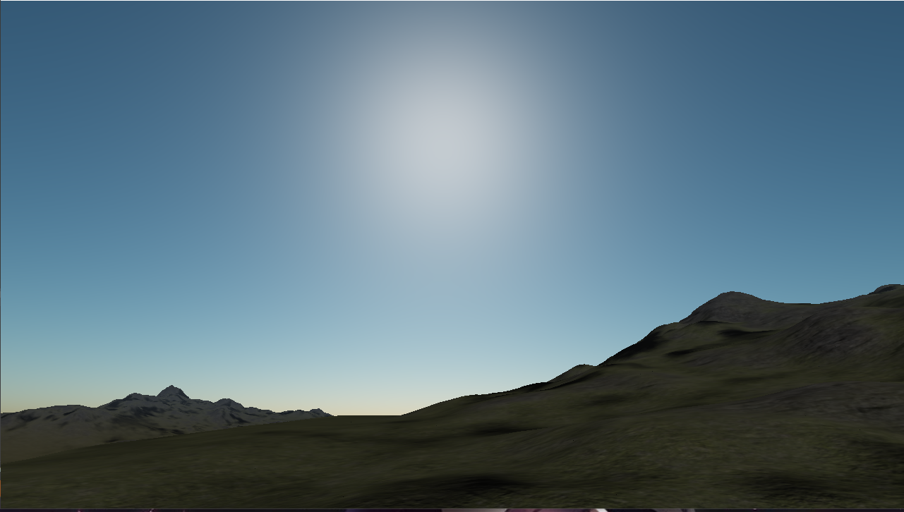
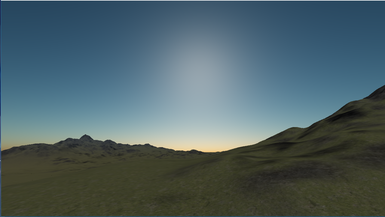
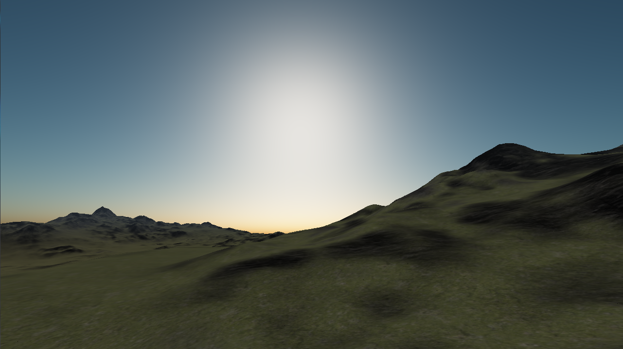
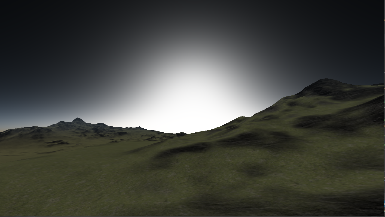
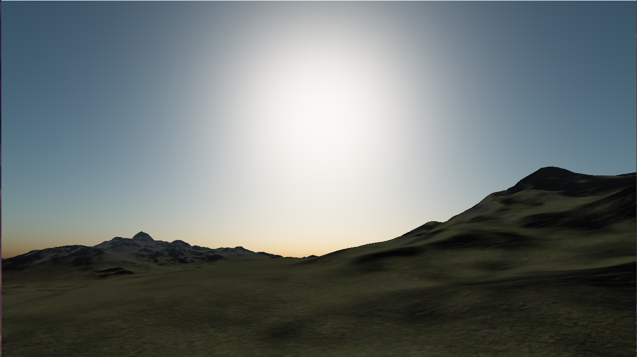
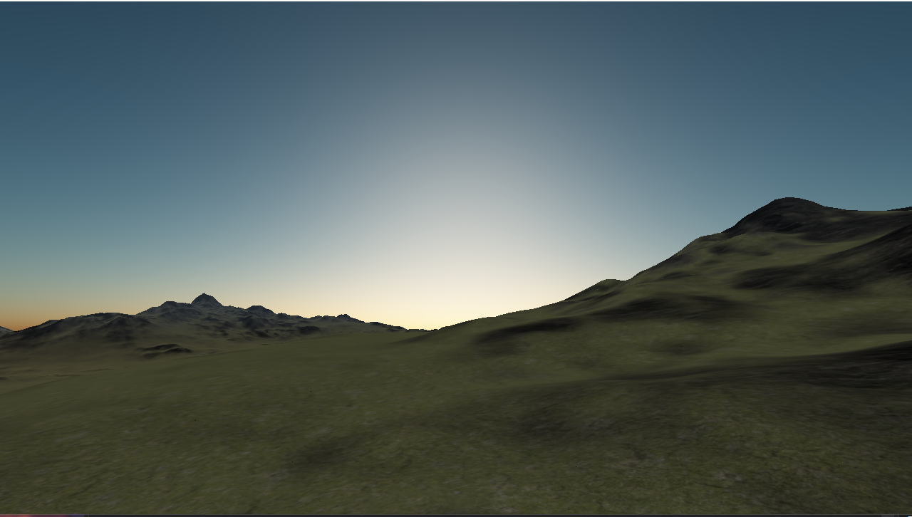
The intensity of the sun. 22.0 is default. Anything from 18.0-30.0 looks reasonable to me. Higher is brighter and lower is darker. This is an interesting lever for changing how the sky looks, as bright or dim stars create interesting atmospheres. Examples at 15, 22, and 30 intensity are shown below.
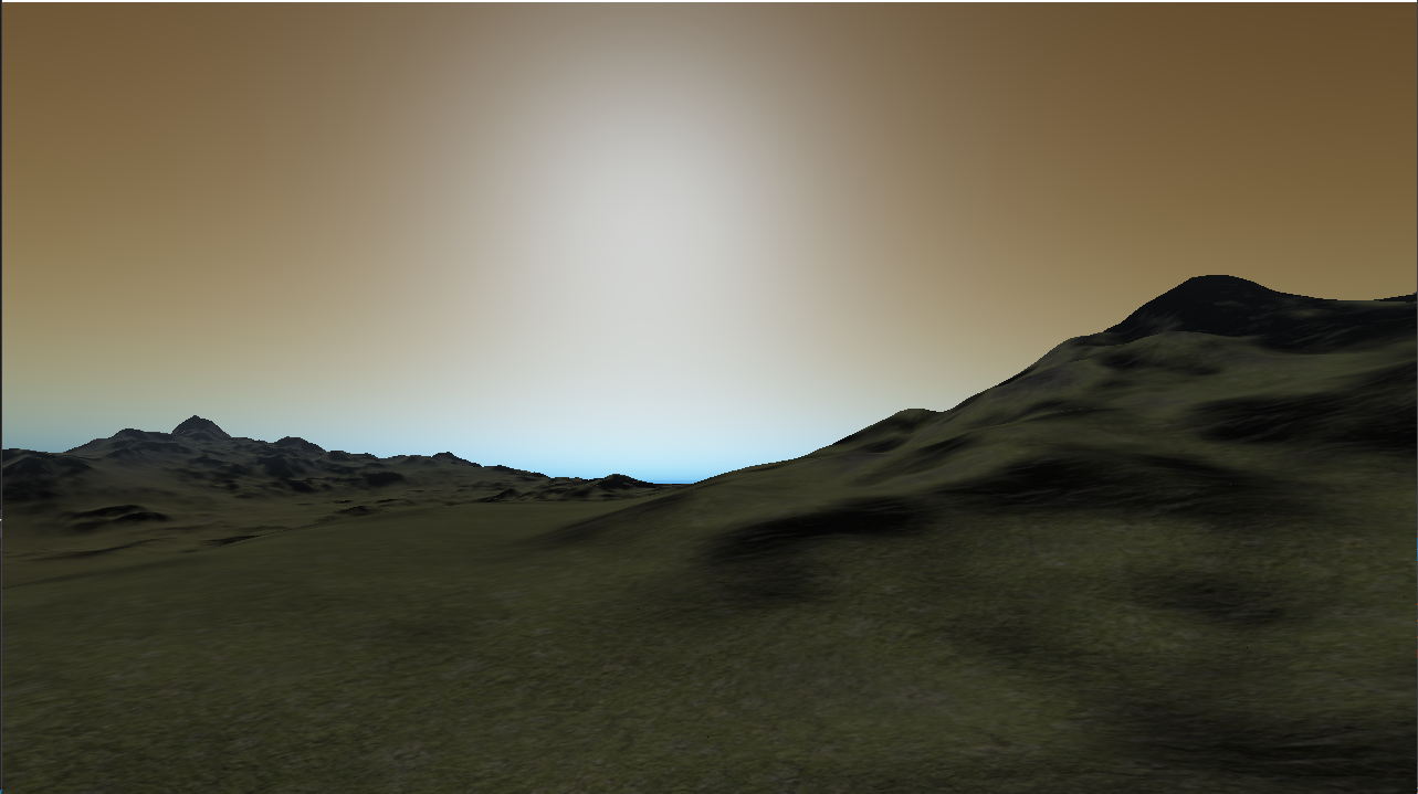
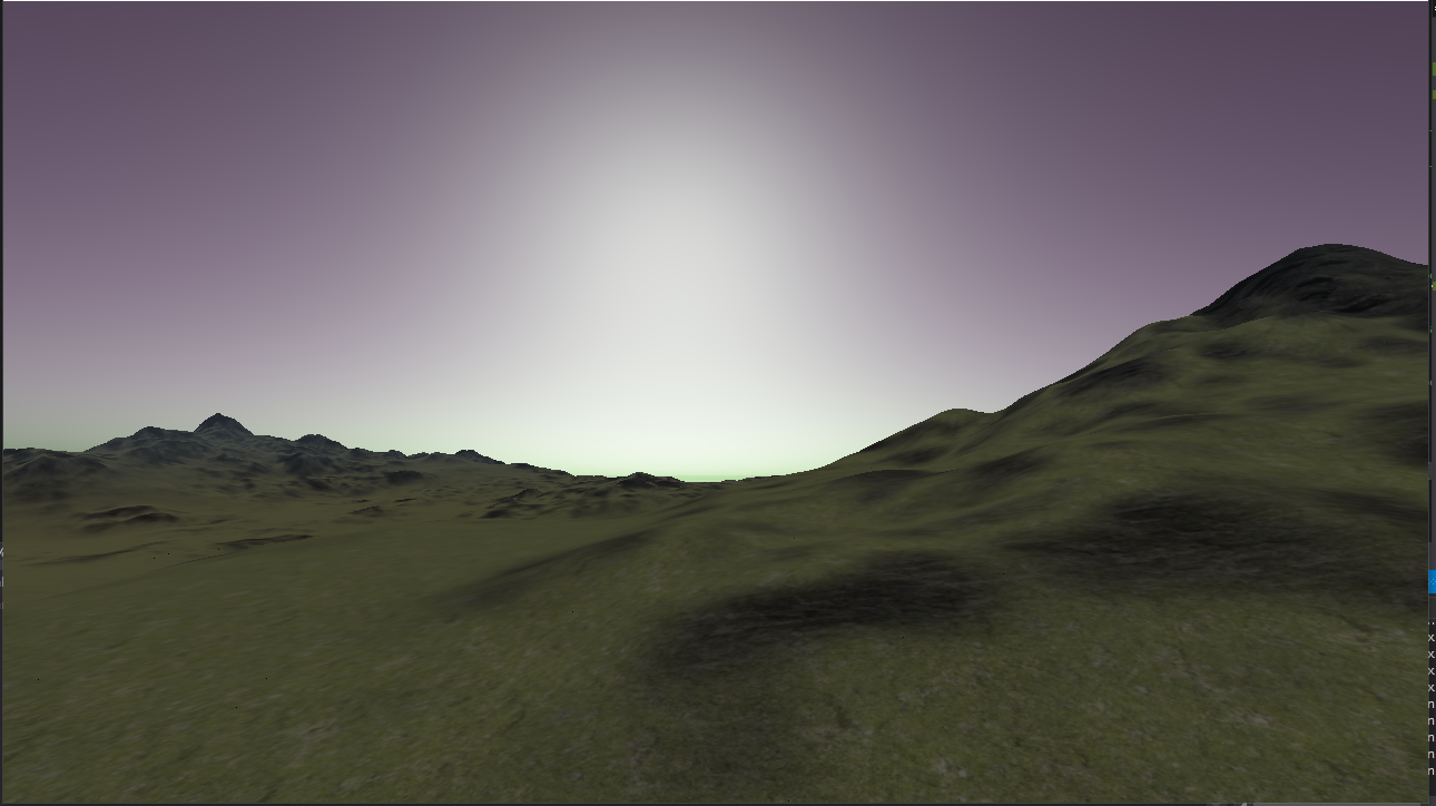
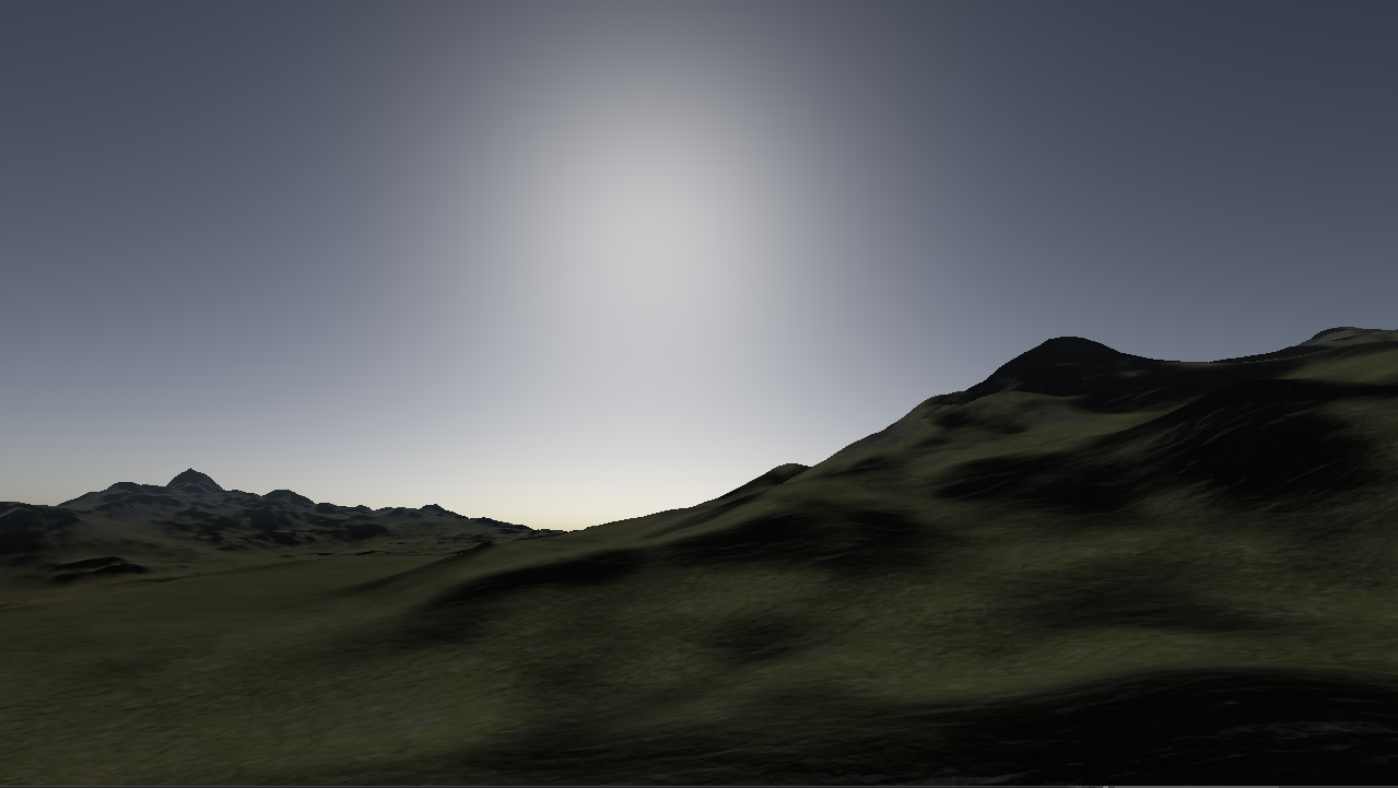
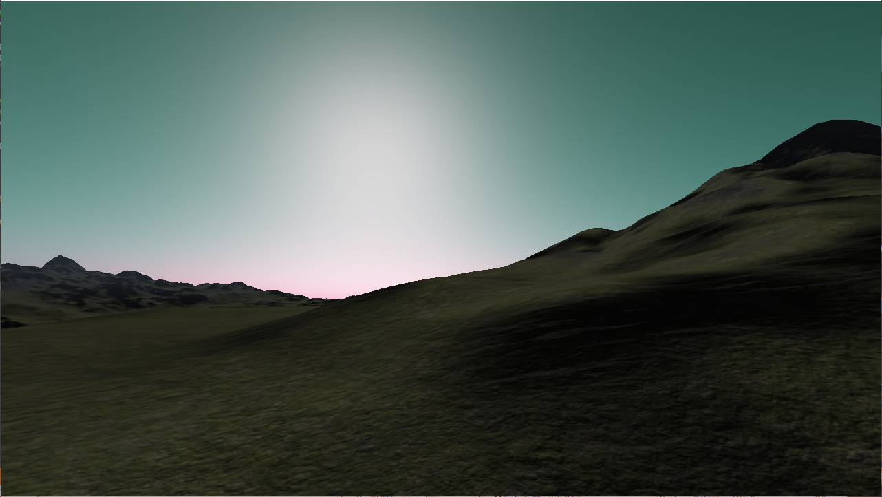
Rayleigh scattering coefficient
How much of each color is scattered in the atmosphere. Play around with these values if you want to change the color of you atmosphere to something other than blue. Larger numbers give stronger colors. The scattering coefficients are given in (R,G,B). Because a star color is not taken as an argument, the color the star appears in the atmosphere can be changed with this value. Below are examples of coefficents (22.4, 13.0, 5.5), (5.5, 13.0, 22.0), (14.5, 10.0, 16.0), (8.5, 10.0, 14.0), and (5.5, 18.0, 14.0). All numbers are missing e-6 from this description.
Mie scattering coefficient
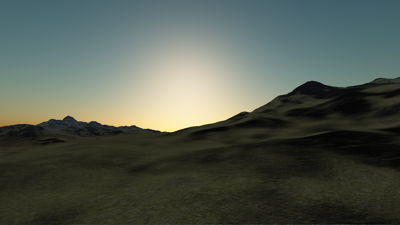
Mie scattering scatters all wavelengths equally, so the larger value here, the more gray the sky will appear. This value also contributes to the overall brightness of the sky and is most noticeable at sunset/sunrise. Below are examples at values 10e-6, 21e-6, and 30e-6:
Rayleigh scattering height
This affects how well dispersed the light is across the atmosphere. Larger numbers appear to be a thicker atmosphere where the light from the star disperses more broadly across the planet, while a smaller number looks like a thinner atmosphere, with less light dispersion and a much darker atmosphere. Below are examples at 1e3, 8e3, and 15e3:
Mie scale height
This value is mostly used to change the size of the star’s glow in the sky. However, higher values tend to make the atmosphere more gray while smaller values make the atmosphere have richer colors. Below are examples at 0.6e3, 1.2e3, and 2.2e3:

Mie prefered scaling direction
This is used to calculate the Mie phase. The color definition of the sun increases with larger values and decreases with smaller values, making the sun appear much more well defined with large values and less defined with smaller values. Below are examples at values .658, .758, and .858:

And finally...
When changing values for this equation, try to stay within an order of magnitude on the Rayleigh and Mie values. They can be interesting to change or randomize with different worlds, but finding good looking ranges for the values should be the main priority.
Tessellation
Most of the work on tessellation was done by Lucas Robertson, and information on this and on the terrain can be found HERE. Only refactoring work was done by myself, and since the functionality has not changed, the explination that he gave for how the terrain works should be sufficent to cover any technical questions about tessilation or the terrain biomes.